As a Mechanical Engineer, electricity and power have always been a touch of a mystery. I can recall my Electrical Engineering classmates talking about things like phase diagrams and other “non-mechanical” things that were fascinating, but very different from what I was studying. Since then, I’ve learned a lot about wiring and power. Having wired the equivalent of two residential homes, and a bunch of other related work: thanks electrician friends for keeping me in check with codes! It’s been fun and has saved me a TON of money. But all of this work has been related to single-phase power.
It wasn’t until earlier this year that I really found need to understand 3-phase power. Having won a local auction for a 1940’s Warner Swasey #2 turret lathe, I knew I needed a single-to-three phase solution. But first I needed to understand the problem domain. In the process of investigating 3-phase power solutions for my shop, I got to know the guys at American Rotary, and have decided to do a complete content series that will cover power fundamentals, types of 3-phase power conversion, my shop install, and running equipment on converted 3-phase power.
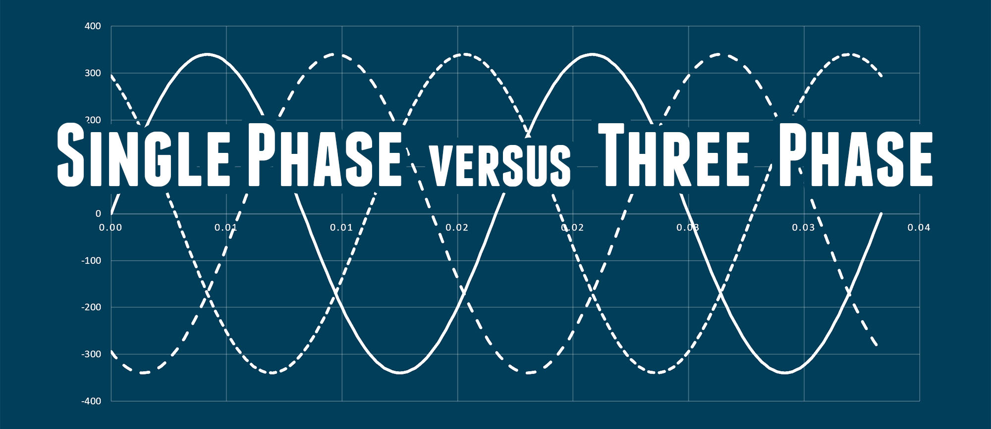
Let’s start here with a comparison and brief (high-level) exploration of both single phase power and 3-phase power!
Single Phase 120 VAC Power
Single phase AC power is what’s most common here in the United States, both for homes and for businesses. It’s the “standard power” for any non-industrial applications. Single Phase AC power uses one “hot leg” which has a voltage that oscillates between a negative voltage (about -170 volts) and a positive voltage (about +170 volts) every 1/60th of a second. It’s therefore called 120VAC 60HZ: 120 Volts Alternating Current, alternating at 60 cycles per second.
Here’s a diagram that shows the lines and wiring for single phase power:
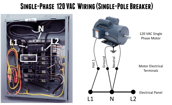
In the above diagram, you can see an actual electrical panel which has three lines: Hot 1 (L1), Hot 2 (L2), and Neutral (N). For 120 VAC appliances (like an electrical motor) only three connections are used:
- One of the two hot legs (L1 or L2) – the “live voltage” leg
- The Neutral – represents zero potential
- Ground (a safety feature for the most part)
Unlike Direct Current (DC), AC oscillates in voltage. It turns out that this oscillation takes the form of a trigonometric Sine wave, something I’m sure you remember from school. Here’s what 120 VAC 60hz power looks like graphed over two cycles:
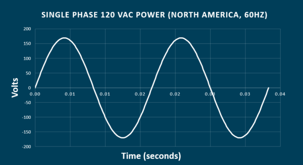
You can see in the diagram, the hot leg voltage oscillates between about +170 Volts, and -170 Volts every 1/60th of a second. The X-Axis (zero) represents the neutral leg. So if the voltage peaks at 170 Volts, why do we call this 120 VAC power? In order to calculate the “average power” (taking each half of the AC power cycle and “averaging” the area under the curve- we need to use a Root Mean Squared (RMS) power formula.
RMS Power Calculation
The RMS formula is simple:
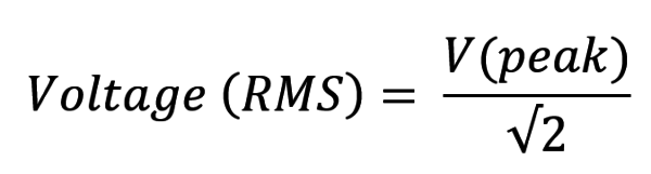
So to confirm we have 120 Volts average power when we peak at 170 Volts, we can see the following relationship:
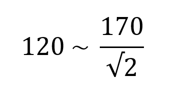
I just checked this with my calculator, so I’m a believer! To summarize, we peak at +170 and -170 volts, each cycle happens in 1/60th of a second, and we average out to 120 Volts AC. Awesome. Now let’s move on to 240 VAC power…
Single Phase 240 VAC Power
With 240 Volts AC power, we have essentially the same situation as with 120 VAC power, except we don’t use the neutral (directly), and instead use the “other hot leg”. This means the potential being measured is across L1 and L2, the two hot legs that are out of phase with each other. Here’s what the wiring looks like for 240 VAC Single Phase:
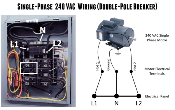
*Note: In some cases a neutral is used when wiring a 240 VAC single phase device, such as when 120 VAC devices are used on-board a machine tool.
At peak voltages, one of the hot legs will read +170 Volts, and the other leg will read -170 Volts- and with our RMS power calculation in hand, we know that this means the total electrical potential is 240 Volts at each peak. Let’s take a look at what this looks like with a graph similar to the one we already looked at:
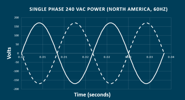
In this diagram, L1 is represented by the solid line, and L2 is represented by the dashed line. In reality, it’s just a matter of timing offset. L1 and L2 are equivalent, but staggered in timing by 1/2 cycle, or 1/120th of a second.
Three Phase Power
Unlike single-phase power which only has one set of “peaks” – three phase power has three distinct peak voltages, one for each of the three “hot legs” that are present in a three phase panel or appliance. Here’s a high-level view of 3-phase wiring:

Here, the operating voltages such as what an electric motor uses to produce power are the differences between adjacent poles in the “triangle” diagram representing three-phase power above.
If you were measuring voltages with a meter, you’d put your test terminals across the following lines:
- Phase 1: L1 and L3
- Phase 2: L3 and L2
- Phase 3: L2 and L1
For an old-school 3-phase motor, the wiring will consist only of the three hot legs: L1, L2, and L3. Newer 3-phase machinery will also have a ground, and possibly a neutral as well. But this article is about the basics of 3-phase power, so we’ll focus on the simple scenario where we are concerned only with the three hot legs.
The three voltage peaks are evenly spaced in time, three peaks per 60 Hz cycle (the frequency we use here in the USA). If we think in terms of angles (natural when you are working with Sine waves) these peaks are separated by 120 degrees. In the time domain, this equates to 1/180th of a second, or about 5.5 Milliseconds.
Let’s take a look at the sine wave diagram for three phase power which peaks at about 340 Volts for 240V 3-Phase power applications:

Above, the following are shown:
- Solid line: L1 (hot leg 1)
- Medium dashed line: L1 (hot leg 2)
- Fine dashed line: L3 (hot leg 3)
Three phase power is great for a number of reasons including:
- Even voltage- the overall voltage never goes to zero like it does with single phase power. This results in more stable rotational velocity for electric motors.
- Variable speed capabilities- the way 3-phase power works, it’s easy to implement variable speed solutions
- 3-Phase motors are typically self-starting, there’s no need for starting capacitor(s)
- Higher power density and conductor efficiency
However, these advantages come at a cost- 3-phase power installs are more complicated, and that’s why they are typically reserved for industrial applications like factories, machine shops, auto shops, and similar environments. But if you want to use 3-phase equipment and don’t have 3-phase service to your house or shop, you’ll need some sort of 3-phase power, and that will be the topic for the next article in this series- types of 3-phase power conversion!
Thanks,
Gavin

Great explain, been looking for this simple intro to 3 phase for year and operated a press on 3ph since 2009… Not i get why it needs it ! thanks. Im also looking to move to a new unit that doesn’t have a 3phase supply here in the UK and think a static converter for the press will be great.
Cheers, Richard in UK