If you’ve run a Bridgeport-style vertical milling machine, you’ve probably worn your arm out cranking the table up and down. I know I have! And now it’s time to add a much-anticipated Z-Axis power feed for my Precision Matthews PM-949TV milling machine!
What’s In the Box
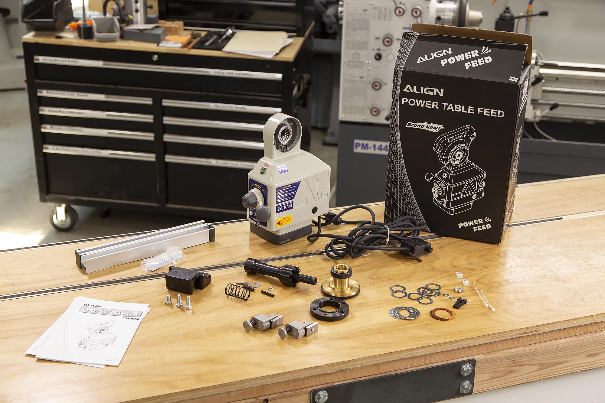
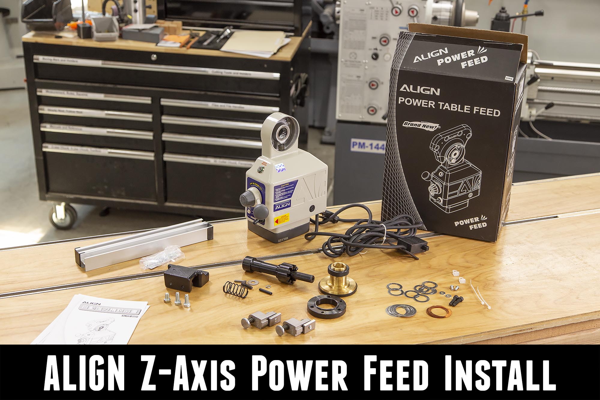
The ALIGN Z-Axis power feed comes with everything you’ll need to install this Z-Axis power feed on most Bridgeport machines, and most clones (including my Precision Matthews PM-949TV).
In the above image we have:
- Power feed unit with power cord and limit switch assembly
- Mounting hardware and shims
- Brass drive gear
- Bearing retainer flange
- Limit switch track and bumper stops
- Knee crank shaft extension, spring, roll pint and hardware
- Limit switch mounting bracket (I did not use)
- Instruction booklet
Mounting the Power Feed
The first steps involve removing some of the factory knee crank components:
- Remove crank handle
- Remove castle nut drive sleeve (may need to be pried off)
- Remove graduated dial lock nut and dial
- Remove inner retention sleeve (I used the woodruff key on the crank shaft with a protective layer of rubber over it + channellocks to help loosen since it was on tight)
- Remove woodruff key from shaft
- Remove bearing retention plate screws and plate
After removing these components, you’ll see something like this:

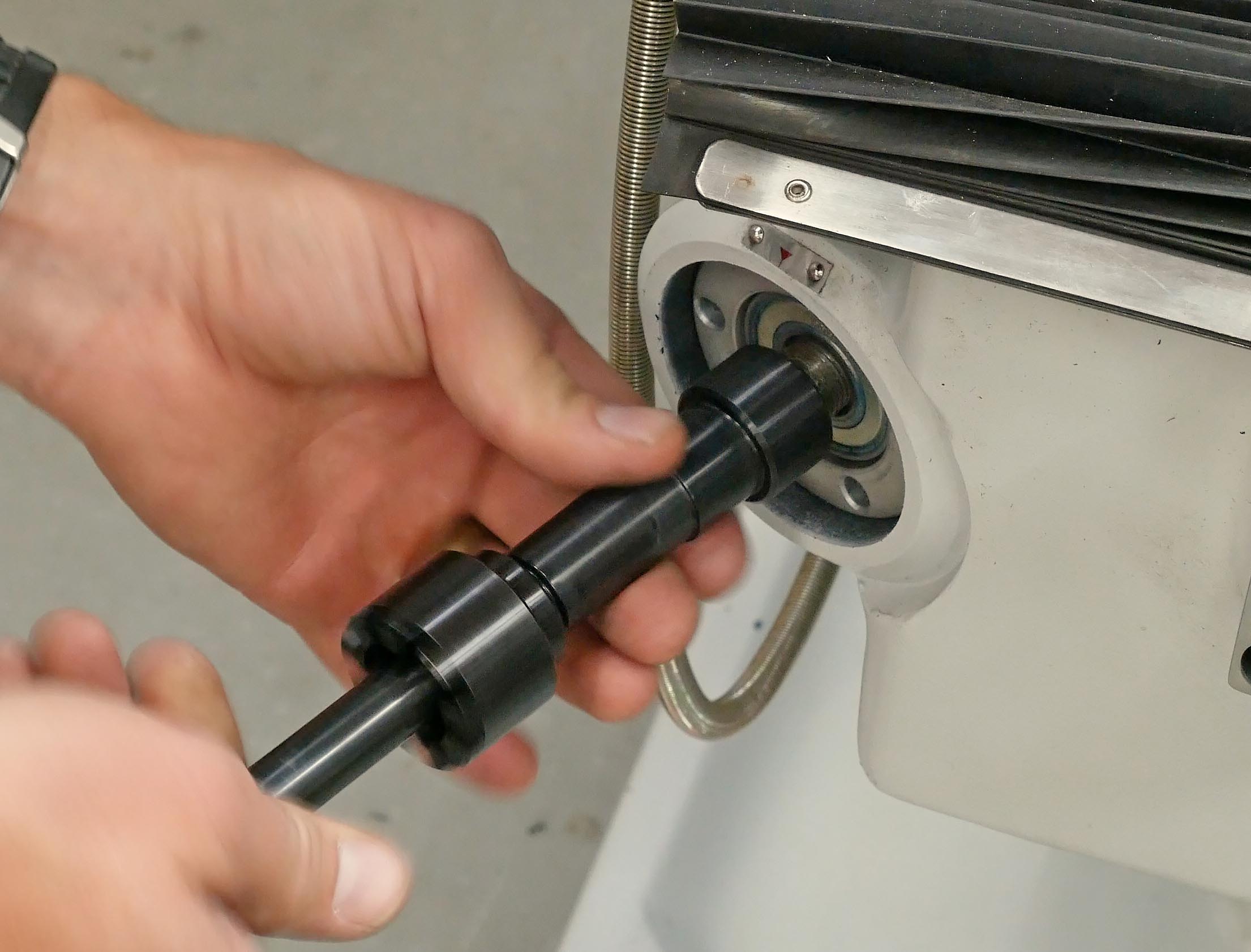
Next, the new z-axis crank and power feed components are installed:
- New shaft extension is installed
- New bearing retainer plate is installed (using factory screws)
- Power feed housing is installed (at angle on PM-949TV to allow for knee clearance)
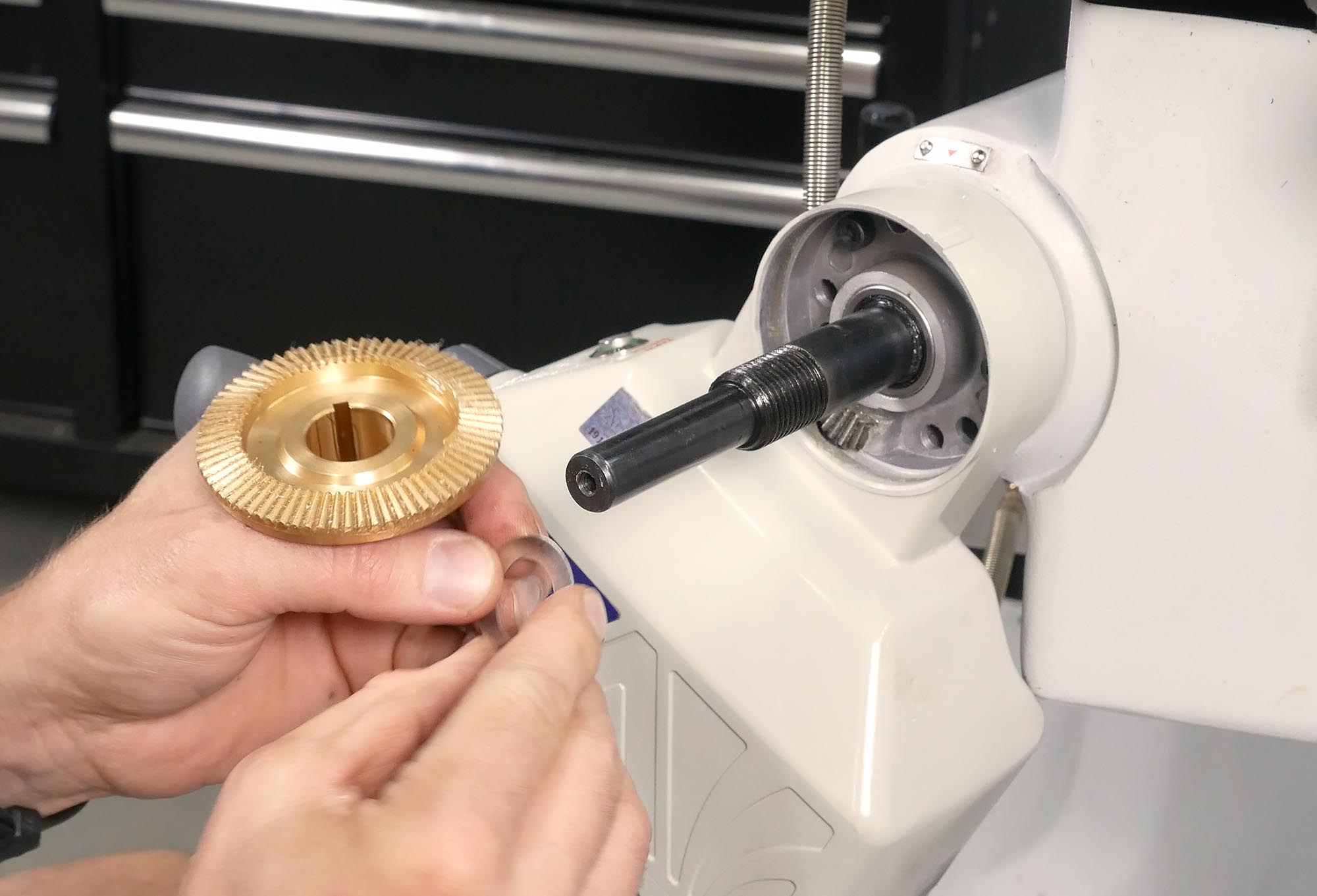
- Bronze drive gear is checked for backlash (WITHOUT WOODRUFF KEY INSTALLED) and shimmed/installed accordingly (with woodruff key)- slight backlash is optimal to prevent binding
- Dial is shimmed for slight gap (between dial and power feed housing) – dial and lock nut are installed
- Castle nut drive sleeve is installed and hand crank + power feed tested for proper function
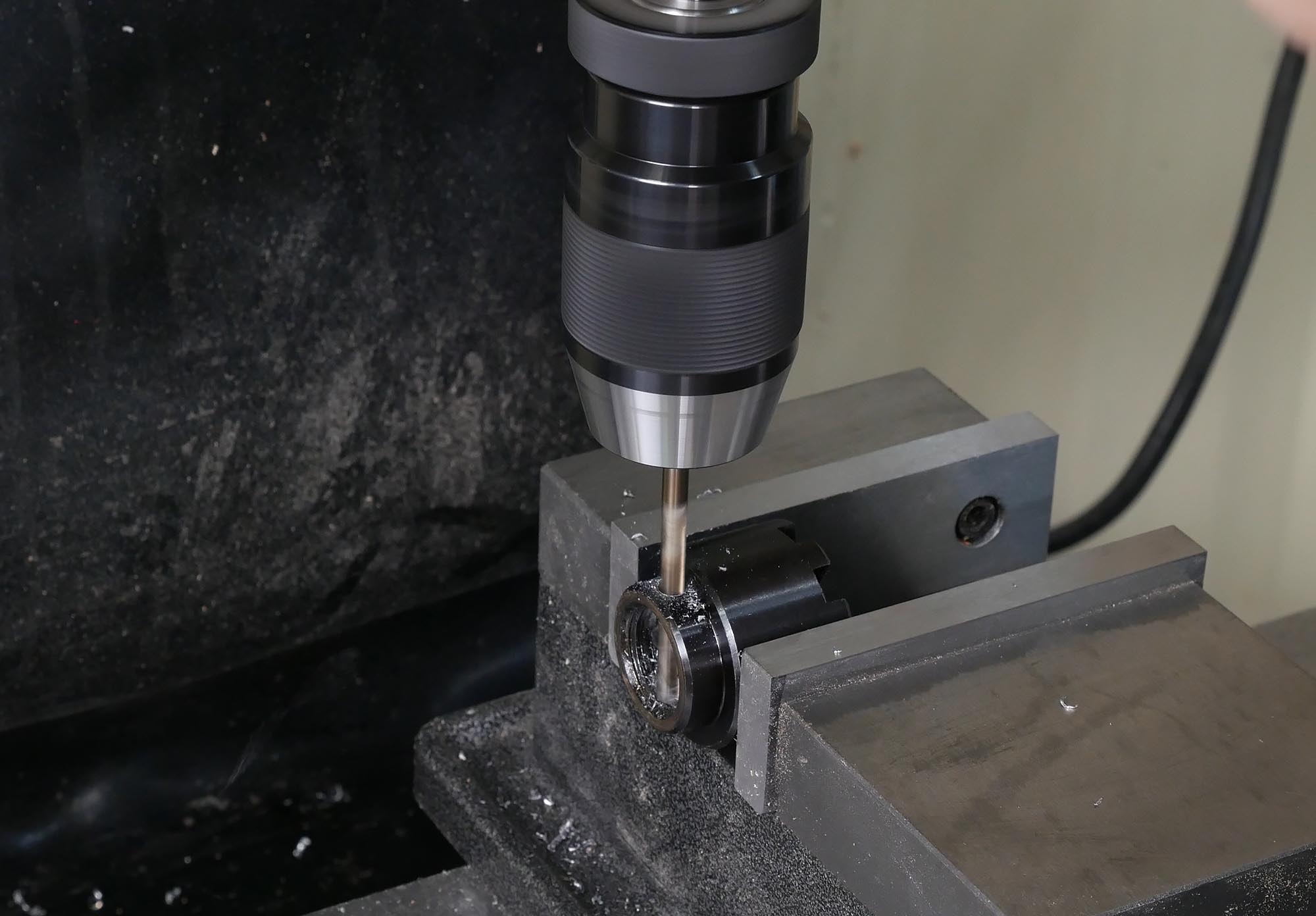
- Optional: Castle nut drive sleeve is removed and cross-drilled on drill press or mill (to guide drill when drilling through shaft extension)
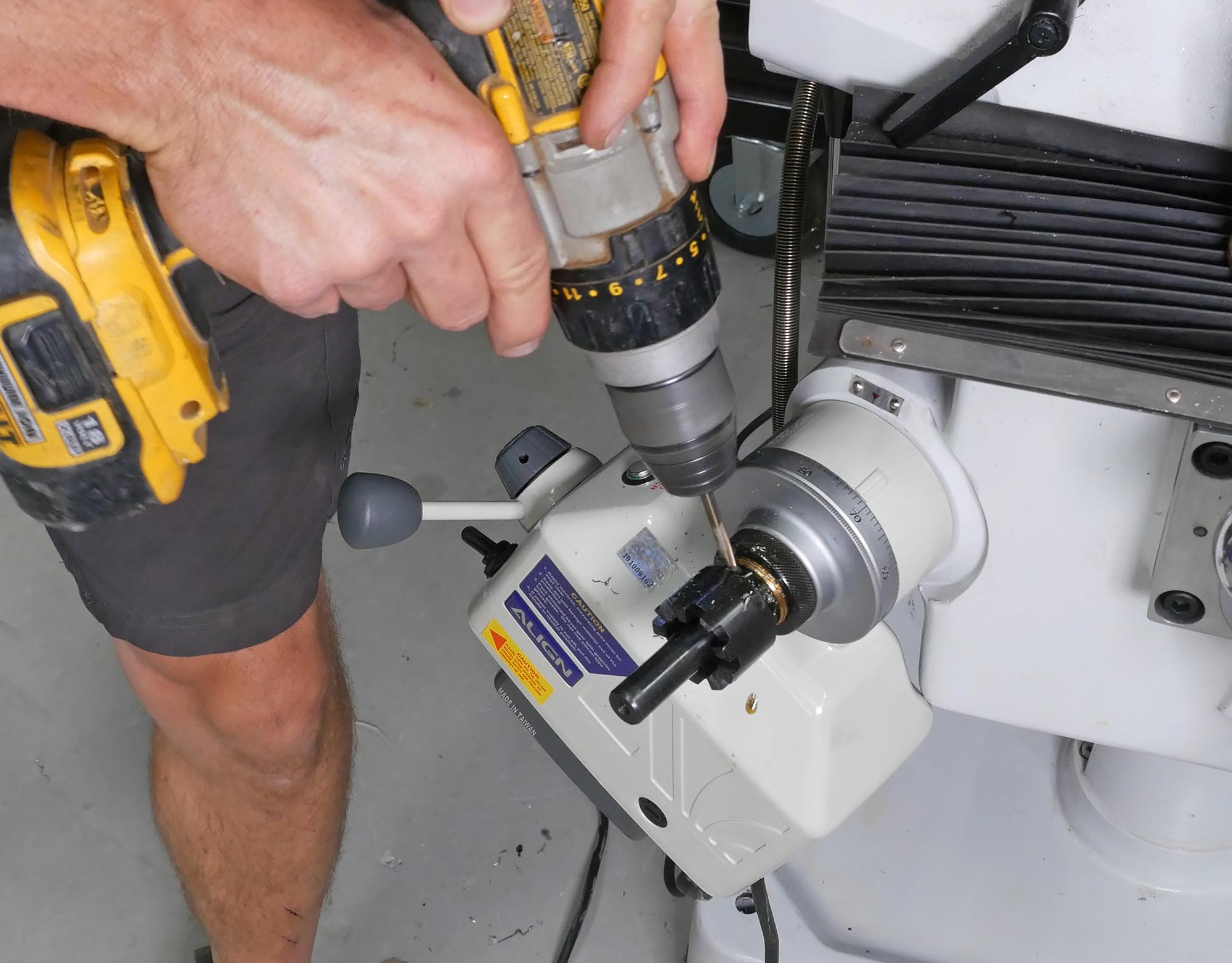
- Castle nut and shaft extension are cross drilled for roll pin
- Roll pin is driven through castle nut and shaft extension
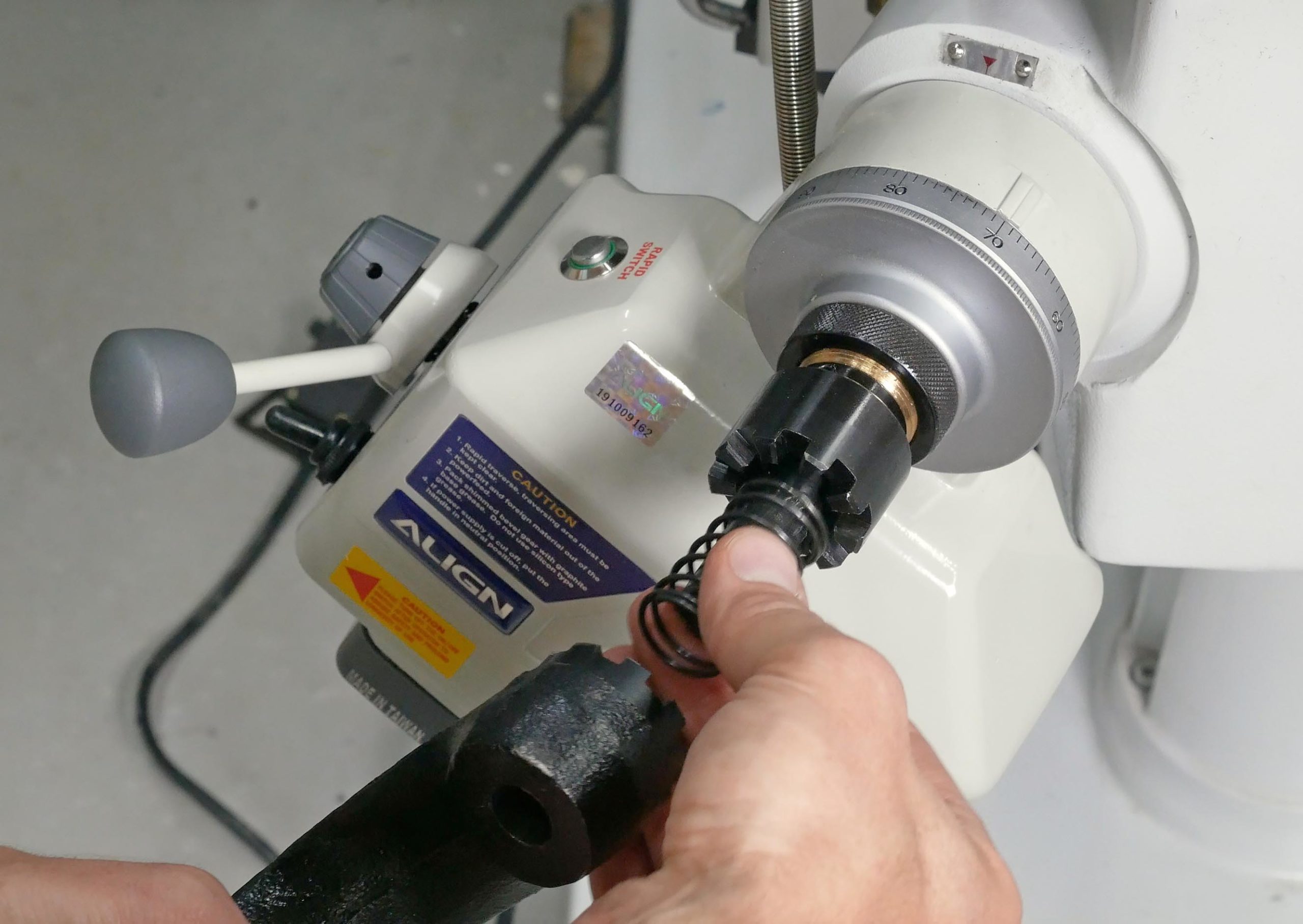
- Handle, disengagement spring, and retention whasher/nut are installed
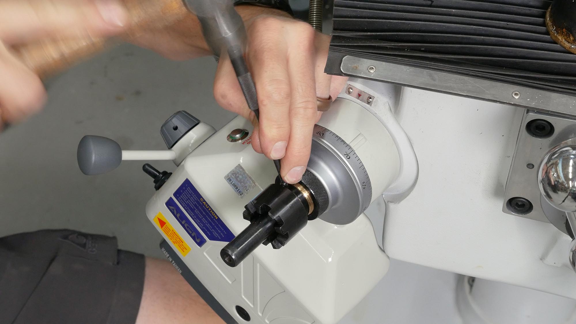
Installing the shaft extension (castle nut can be removed prior to this):
Shimming and installing bronze drive gear:
Shimming and installing dial:
![]()
Cross drilling castle nut: (after proper fit verified on mill)
Cross drilling shaft extension:
Driving roll pin:
Installing disengagement spring, handle, washer and retention screw:
Mounting the Limit Switch and Stops
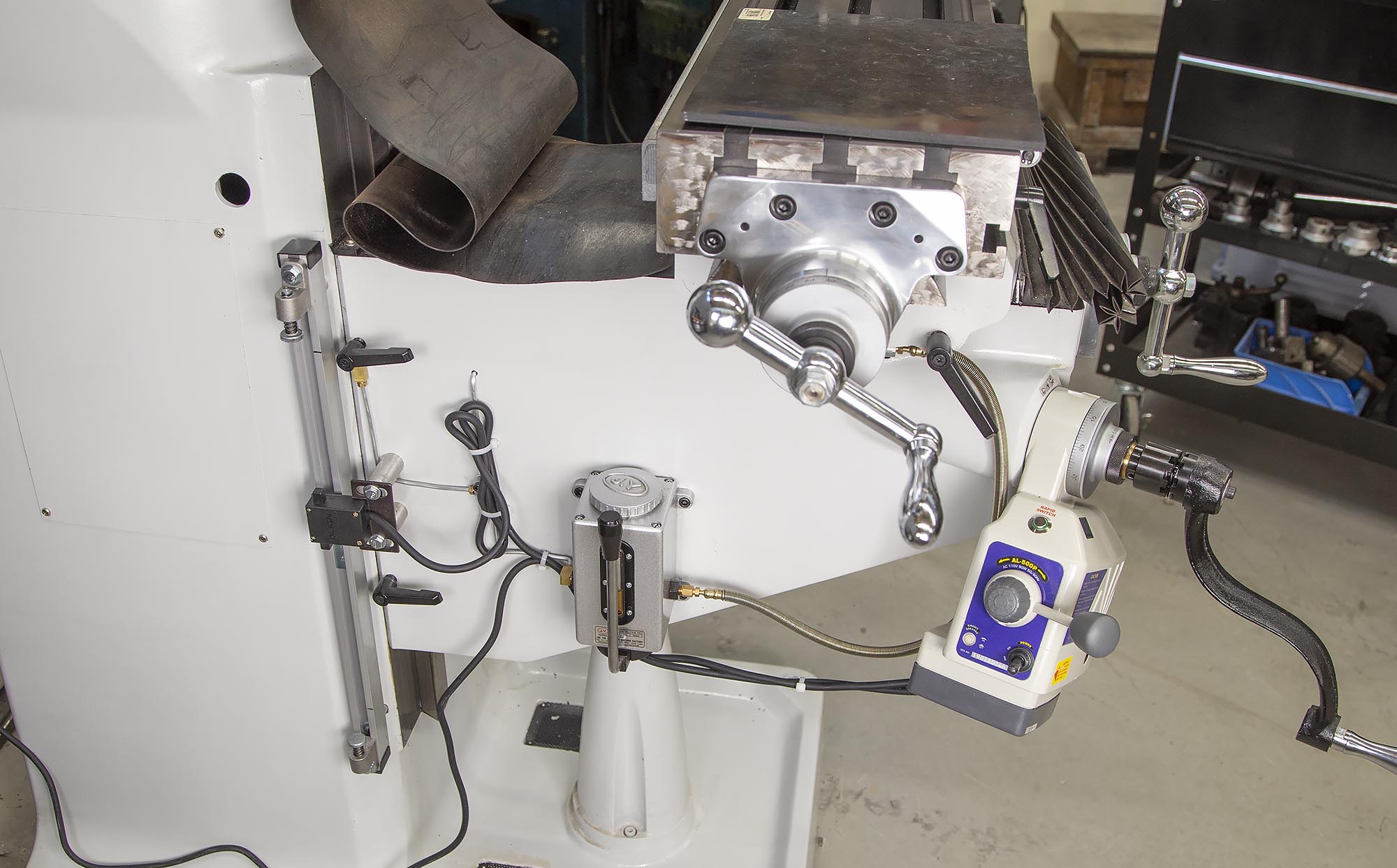
There are multiple ways to setup the limit switches and stops on your mill. Precision Matthews installs them as a part of the DRO scale setup on the left-side of the knee. I wanted to install these limit switches separate from the DRO hardware so as to not knock things around when the limits are hit.
My install (as shown in the image above) was performed as shown in the video:
- Assembled track
- Measured travel range using pencil marks on knee and column
- Counterbored and drilled/tapped (1/4″ x 20) column to provide flat area to mount standoff (bottom mounting screw for track)
- Machined track standoffs on my lathe
- Installed bottom mounting screw, standoff, and track
- Used transfer punch to mark top screw hole location
- Drilled and tapped (1/4″ x 20) upper mounting hole
- Installed upper stand-off and mounting screw
- Flattened limit switch bracket
- Measured locations for holes and depth for standoffs
- Machined standoffs for limit switch bracket
- Drilled and tapped holes (1/4″ x 20) for limit switch mounting bolts
- Installed limit switch assembly, standoffs, and mounting screws
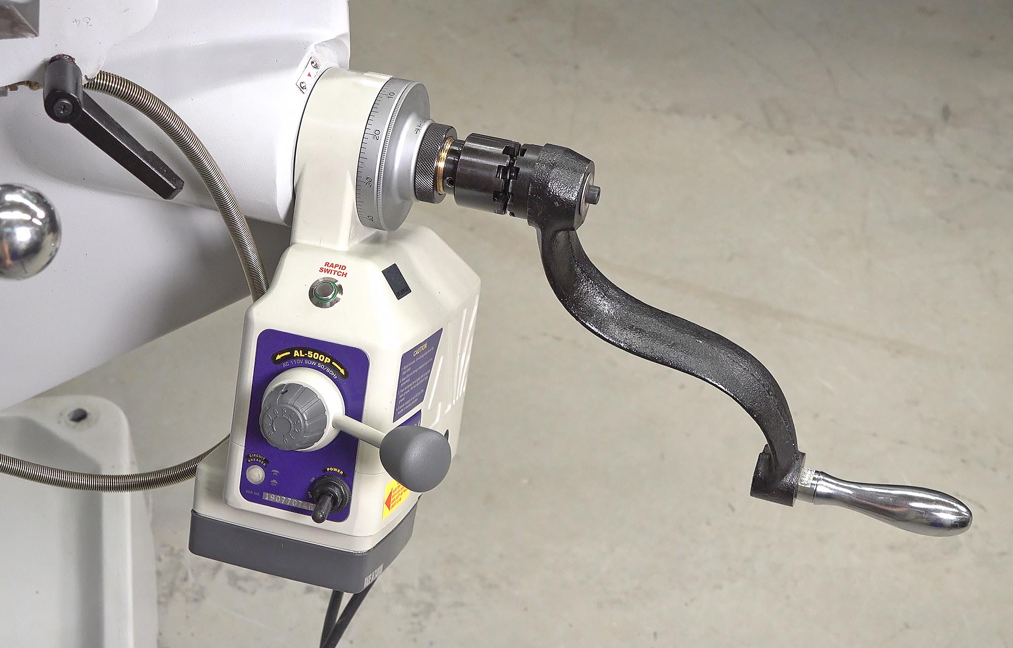
Testing Function
With the power feed installed, it was time to test everything:
- Up and down (variable speed)
- Up and down rapid traverse
- Hitting limit switches (both up and down) during rapid traverse, checking for movement on limit switches, stops, etc
- Hand cranking up and down
Everything turned out perfect! And I’ve already used this Z-Axis power feed on a couple projects- it’s a game-changer!
Don’t miss out on Ultimate Reloader updates, make sure you’re subscribed!
Thanks,
Gavin